This post covers the details of how I made a flight controller for a quadcopter using Rust and an STM32.
Introduction
This project began as a desire to familiarize myself with embedded development. I wanted to challenge myself by using technology I was not familiar with or had no prior knowledge of. This led me to the idea of making a Rust-based quadcopter. I will walk through the different components and software I used to realize this project.
Components
To simplify things on my end, I decided to buy a drone kit that came with the following items:
Chassis
4 30A Electronic Speed Controllers
4 BLDC Motors
4 Propellers
Screws & Bolts
Other components needed:
STM32F411CEU6
FlySky Transmitter & Receiver
LiPO Battery
IMU (LSM6DSOX)
Rust
Rust is a systems programming language designed to prioritize performance and stability. It is particularly advantageous for embedded development due to its extensive community support. There are Hardware Abstraction Layers (HALs) available for various microcontrollers, including several STM32 models. Notably, the svd2rust crate enables users to convert SVD files into crates, providing APIs to access the microcontrollers’ peripherals
I am using the STM32F411CEU6 for my flight controller, so I will be using the stm32f4xx-hal. Another important crate in the embedded-rust community is probe-rs which provides a direct interface to various embedded MCUs and debug probes, eliminating the GDB layer unlike similar projects such as OpenOCD.
Real-Time Interrupt-Driven Concurrency
RTIC is a Rust-based framework that allows real-time interrupt-driven concurrency for ARM Cortex-M microcontrollers. It is similar to an RTOS in that they both perform scheduling. Where they differ is that RTIC uses the hardware on the Cortex-M MCUs to perform the scheduling instead of a scheduling kernel.
IMU & Kalman Filter
IMU, short for inertial measurement unit, can measures the angular rate and acceleration of a quadcopter’s roll, pitch, and yaw. These measurements can be used to determine the attitude (roll, pitch, and yaw) of my flight controller.
The IMU I will be using, the LSM6DSOX, consists of a gyroscope and accelerometer. The gyroscope allows for the measurement of the angular rates of the IMU’s roll, pitch, and yaw axes. The accelerometer allows for the measurement of the acceleration of the IMU’s roll, pitch, and yaw axes.
This IMU supports I2C and SPI communication protocols. These protocols allow for communication with other devices. In my case, I need to send the reported measurements from my IMU to the STM32. While the list of I2C and SPI drivers written in Rust may be extensive, there was not one yet for the LSM6DSOX as of the date of this project, so I wrote my own I2C driver.
Before writing an I2C driver in Rust, I first took a look at how other drivers were created in Rust. This is a pretty good list to look at. It even contains a few drivers for other IMUs.
Most of them were built on top of the embedded-hal crate. This crate serves as a foundation for building platform-agnostic drivers, allowing a driver to work on a microcontroller regardless of its platform.
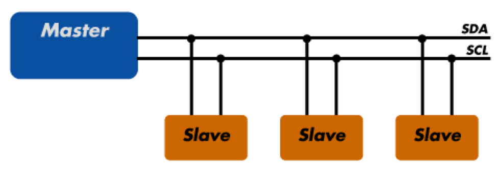
Before I go further into details about my I2C driver, a basic understanding of the I2C protocol might be helpful. The I2C protocol uses two wires for serial communication between a Master and a Slave. These wires are labeled the serial data line (SDA) and the serial clock line (SCL). The first line is for data transfer and the second line is for communication. When attempting to read data through the SDA bus, it is first necessary for the Master (or the STM32 in my case) to write the address of the slave onto the bus it wants to read from. This is necessary so that any slave can respond if they have the corresponding address.
This was a very basic overview of the I2C protocol, and a lot of the underlying mechanisms of how it works were not covered, mainly because the embedded-hal crate does a great job at abstracting away the underlying details.
With that basic understanding of the protocol, my driver will make more sense. In order to get the gyroscope and accelerometer values, I just have to write the address of my IMU on the I2C bus, and then read from the address of the register that stores the desired data. To find the IMU slave address, and the address of the registers where the data is stored, I had to read the LSM6DSOX datasheet. I have created two files, gyro.rs and accel.rs, to contain the registers necessary to read their values.
The code above serves to implement a struct Lsm6dsox with a parameter I2C such that I2C has the methods WriteRead and Write.
1 2 3 4 5 6 7 8 9 10 11
pubfnconfigure_accel(&self, i2c: &mut I2C) ->Result<(), E>{ // ODR_XL[7:4] = 0100; sets accelerometer to work at 200 Hz // FS[3:2] = 10; sets accelerometer full-scale selection to 4g // LPF2_XL_EN[1] = 1; output from first stage digital filtering // 0100 10 1 0 letconfiguration: u8 = 0x48; match i2c.write(SLAVE_ADDRESS, &[CTRL1_XL, configuration]) { Ok(_) => Ok(()), Err(e) => Err(e), } }
In the function above, I configure the accelerometer in my IMU. Referring to the datasheet, I observe that each bit in the configuration register influences aspects such as the frequency of readings. I utilize the write method to send the 8 bit value configuration to the CTRL1_XL register of the device, specifying the slave address as SLAVE_ADDRESS. The process of configuring the gyroscope mirrors that of the accelerometer, albeit with different configuration values and register addresses.
1 2 3 4 5 6 7 8 9 10 11 12 13 14 15
// Read Accelerometer Data pubfnread_accel(&mutself) ->Result<[f32; 3], E> {
In the function above, I am reading accelerometer data. Each axis’s data is represented with 16 bits, spread across 2 8-bit registers. To get each axis’s value, I read from 6 consecutive registers (3 axis multiplied by 2 register per axis). The write_read method writes SLAVE_ADDRESS to the I2C bus and reads enough bytes from the device with the address of SLAVE_ADDRESS to fill buffer in one go. This reads all accelerometer registers if buffer has 6 bytes. The IMU is configured by default to automatically increment a register address during a multiple byte access with a serial interface.
Accelerometer data for each axis is 16-bit. The IMU stores the 8 most significant bits in one register and the 8 least significant bits in another. For the accelerometer, OUTX_H_A is the MSB for the X-axis, and OUTX_L_A is the LSB. I left shift buffer[1], buffer[3], and buffer[5] by 8 bits, and bitwise OR these values with their corresponding LSBs to reconstruct each axis’s value.
Deriving the Attitude
So I’m able to get the angular rates and acceleration of each axis using my IMU. But how can this be used to get the angles of roll, pitch, and yaw axis? I’ll discuss two ways of obtaining the attitude from the gyrscope and accelerometer.
Angular rate is just the rate at which the angle changes in a moment of time. By integrating this value, we can get the the angle of each axis. Integration in the context of a microcontroller would have to be discretized. This simplifies the calculations a lot. To get the angle of an axis, you would do a summation of the corresponding angular rate multiplied by the delta time. In our case, the delta time would be the amount of time elapsed between the previous and current loop.
x_gyro += delta_sec * gyro_data[0]; // Angle of flight controller in the x-axis y_gyro += delta_sec * gyro_data[1]; // Angle of the flight controller in the y-axis z_gyro += delta_sec * gyro_data[2];
prev_time = time; }
While this method works in the short term, you will notice that the angles derived from the gyrscope drastically loses any accuracy as time progresses. This is due to the fact the there is an uncertainty in the readings of the angular rate, and as we integrate these uncertainties, the error will accumulate.
The second method is using the accelerometer. As previously mentioned the accelerometer measures the acceleration of each of its axis (X, Y, and Z). At rest, the Z axis will report a value of around ~ 1 (measured in g’s). If the IMU is in a different orientation, each of its axis will experience a different portion of gravity. Plugging these values into trigonometric equations can give us the orientation of the IMU in terms of degrees of each of its axis except for the z-axis. The z-axis cannot be calculated as this is inherent limitation to an accelerometer.
While the results from an accelerometer are mostly accurate, in moments of high vibrations the values are basically useless as there is too much noise.
So we have a scenario in which the gyrscope’s data is useful in the short-term, but useless in the long-term and the vice-versa for the accelerometer’s data. A Kalman Filter is perfect for this scenario.
What is a Kalman Filter?
The Kalman filter is an algorithm used for estimating the state of a system in the presence of noisy measurements. It works by iteratively predicting the next state based on a dynamic model and comparing it with actual measurements. The filter optimally combines predictions and measurements, dynamically adjusting their contributions based on their uncertainties. This allows the Kalman filter to provide a more accurate and stable estimate of the system’s true state, making it widely used in applications like sensor fusion for robotics, navigation, and control systems.
In my case, I can use it to fuse the data from the accelerometer and gyroscope that can minimize their respective downfalls to produce a more accurate result. I found this blog by TKJ Electornics to be very helpful in understanding how a Kalman Filter can be applied to a 6-axis IMU.
ESC
The electronic speed controller is a simple piece of circuit that controls the speed of the motors. There are a few methods to communicate with the ESC from my microcontroller to dictate the speed of the controllers. I will be using the simplest method, PWM signals.
What is PWM?
Pulse-width-modulation is essentially rectangular wave signal with a duty cycle and period. A duty signal is the percentage of the signal that is active. A period is the time between each succesive occurence.
For my ESC, I can dictate the desired speed of my motors by sending a 50Hz PWM signal. When the active portion is 1ms, the ESC interprets that as zero throttle. When the active portion is 2ms, the ESC interprets that as full throttle. Any signal with an active portion between 1ms to 2ms will set the speed proportionately. For example, a PWM signal with an active portion of 1.5ms will set the throttle to half the max speed.
For my ESC to work, it needs to initially register a zero throttle signal before it can receive any other signal.
PWM Implementation
I first needed to setup the timer channels. Each timer in the STM32 has two channels assosiated to itself. Thus, each timer can generate two differnt PWM signals. For your microcontroller, you must check the pinout sheet to see which pins to use.
In the stm32f4xx-hal, the set_duty method requires a value rather than a percentage. To send a zero throttle signal, I need to determine the duty cycle with an active portion of 1ms.
Given that a 50 Hz signal has a period of 20ms, the duty cycle for a zero throttle signal would be 1ms / 20ms, which equals 0.05. Therefore, to achieve a zero throttle signal, I multiply the maximum duty cycle by 5 / 1000, or equivalently, divide it by 20.
For the maximum throttle signal, the duty cycle would be 2ms / 20ms, which equals 0.1. Thus, the corresponding maximum throttle signal would be the maximum duty cycle divided by 10.
Additionally, I introduce a slight delay to allow the ESC to register the zero throttle signal. I can confirm this works because I hear specific beeps in a distinct melody.
For my remote controller, I am using the FlySky FS-IA6B. It comes with the transmitter and a receiver. All I had to do is read any bytes incoming from the receiver. FlySky has a feature called the IBus protocol, which essentially allows it to send the data of all the channels in 32 byte packets through the UART hardware.
Note A channel in this context refers to each inputs on the transmitter, such as the joysticsk and switches.
To my luck, the stm32f4xx-hal repository already contains an example with UART and RTIC. This example uses a UART interrupt to immediately notify the CPU when the UART has new information.
Unfortunately, getting this to work for my usecase proved to be quite difficult. The UART would constantly get new data so it would starve the other tasks. Instead, I switched to polling the UART for new info and implemented a checksum verification to discard erroneous packets.
Note Interrupts allow hardware to notify the CPU of a specific event. Polling is when the CPU checks on the hardware for any new events. This comes at the cost of additional CPU clock cycles.
while index != 32 { ifletOk(byte) = rx.read() { if index == 0 && byte != 32 { // Ignore bytes until the first byte is 32 (space character) continue; } bytes[index] = byte; index += 1; } }
foriin (0..bytes.len()).step_by(2) { if i + 1 < bytes.len() { // Extract two bytes from the pair letbyte1 = u16::from(bytes[i]); letbyte2 = u16::from(bytes[i + 1]);
if i < 30 { checksum += byte1 + byte2; }
// Combine the bytes by multiplying the second number by 256 //let combined_value = u16::from(byte1) + u16::from(byte2) * 256; letcombined_value = byte1 | byte2 << 8;
letchannel_index = i / 2; //rprintln!("index: {:?}", channel_index); // Do something with the combined value (e.g., print or use it)
Err(_err) => { // Other errors occurred, handle them appropriately // Example: println!("Error occurred while enqueueing data: {:?}", err); rprintln!("Flysky failed to enqueue"); } } }
}
PID
A pid is a control loop concept that can use feedback to adjust the inputs to drive the system towards a desired state. I will be simplifing how PIDs work a lot as I probably won’t do a good job at explaining its complexities.
For my drone, I am able to get the attitude of my drone, and I can set the desired attitude with my remote controller. I need some sort of mechanism to force the drone to match the attitude set by the remote controller. A PID controller can do so by constantly adjusting the speed of each motor to match the desired angle. A PID must be configured to work properly by tuning its three parameters; proportional, controller, and integral.
Proportion
The porportional or P-controller takes a fraction of the error. For example, the pitch of my drone may be 15 degrees, but my desired pitch could be 0 degrees. The error would be 15 degrees. The proportion would multiply this error by a factor to adjust the input throttle to each motor.
Integral
The integral or I-controller helps with small errors by taking a fraction of the integral of the error.
Derivative
This controller takes into account on how rapidly the error is changing by taking a fraction of the error’s derivative.
RTIC
RTIC, as mentioned previously, is a real-time framework. In the context of embedded software, a real-time system is defined as one that is deterministic and meets specific timing requirements. This is in contrast to systems like Arduinos, which rely on one large loop. While Arduino-based quadcopters have been developed before, using a real-time framework like RTIC can provide greater reliability in certain scenarios. Determining which approach is better depends on the use case.
RTIC includes a scheduler that determines which task to run by programming the MCU’s hardware. In my project, I have three tasks. The first task polls the UART for new data. The second task employs the Kalman Filter to determine the drone’s attitude from the IMU data. The third task is the flight controller task, where I use a PID controller to generate the appropriate throttle signals for each motor. Each task operates as an interrupt service routine of a timer, allowing them to run approximately every 15ms with high accuracy. RTIC also includes an init task, responsible for configuring all the hardware and setting initial values.
#[app(device = stm32f4xx_hal::pac, dispatchers = [SPI1, SPI2])] mod app { use core::f32::consts::PI; use heapless::spsc::{Consumer, Producer, Queue}; use rtic_monotonics::{create_systick_token, systick::Systick}; use stm32f4xx_hal::{selfas hal};
while index != 32 { ifletOk(byte) = rx.read() { if index == 0 && byte != 32 { // Ignore bytes until the first byte is 32 (space character) continue; } bytes[index] = byte; index += 1; } }
foriin (0..bytes.len()).step_by(2) { if i + 1 < bytes.len() { // Extract two bytes from the pair letbyte1 = u16::from(bytes[i]); letbyte2 = u16::from(bytes[i + 1]);
if i < 30 { checksum += byte1 + byte2; }
// Combine the bytes by multiplying the second number by 256 //let combined_value = u16::from(byte1) + u16::from(byte2) * 256; letcombined_value = byte1 | byte2 << 8;
letchannel_index = i / 2; //rprintln!("index: {:?}", channel_index); // Do something with the combined value (e.g., print or use it)
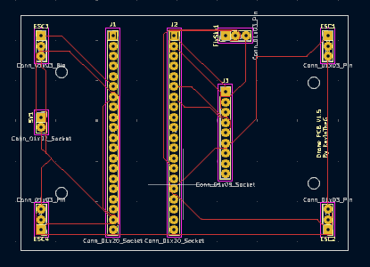
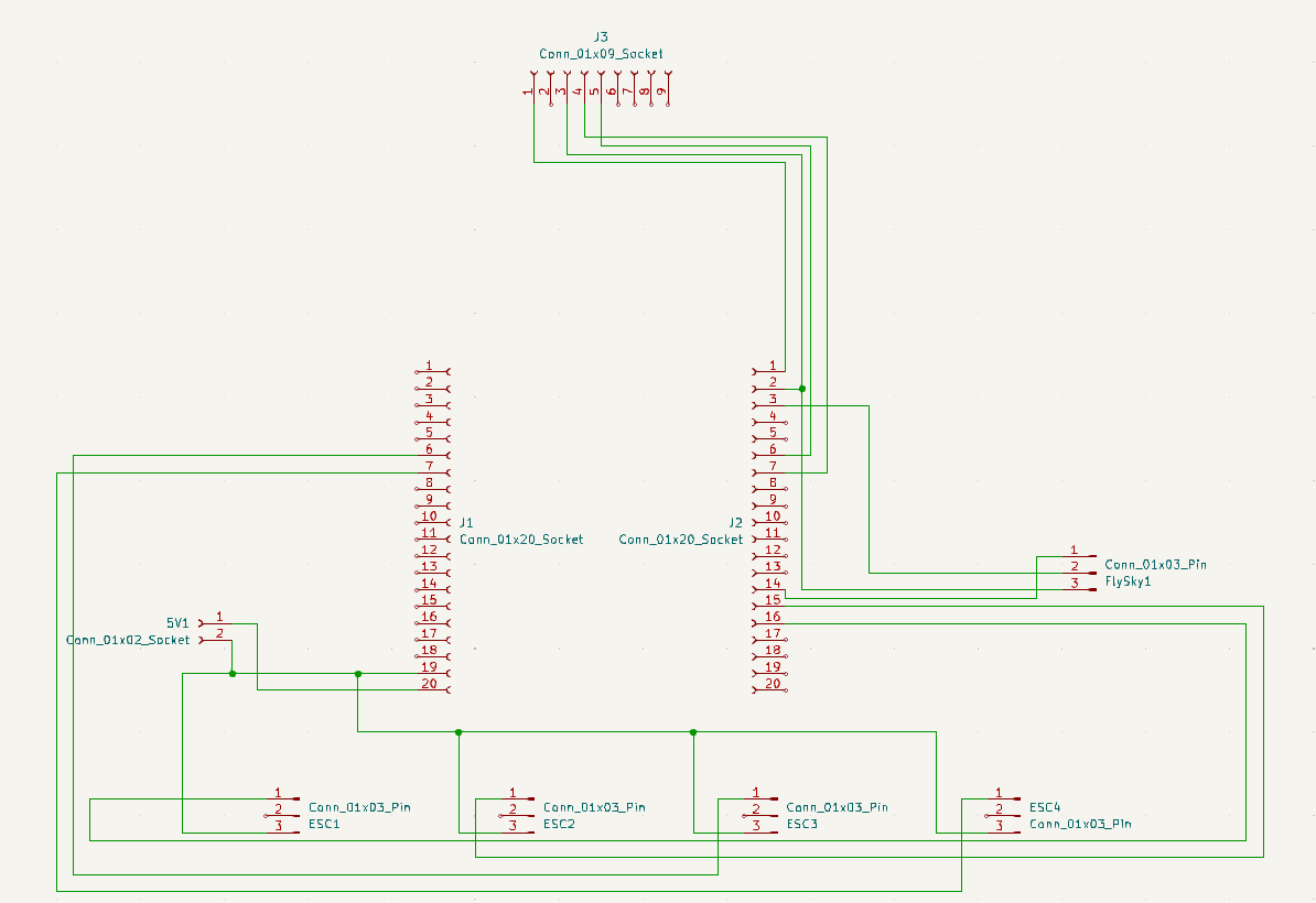
I initially used a breadboard for prototyping and testing each component. Afterwards I got each component working together, I designed a PCB to make connections for the ESC, IMU, FlySky Receiver, and the microcontroller on one board.
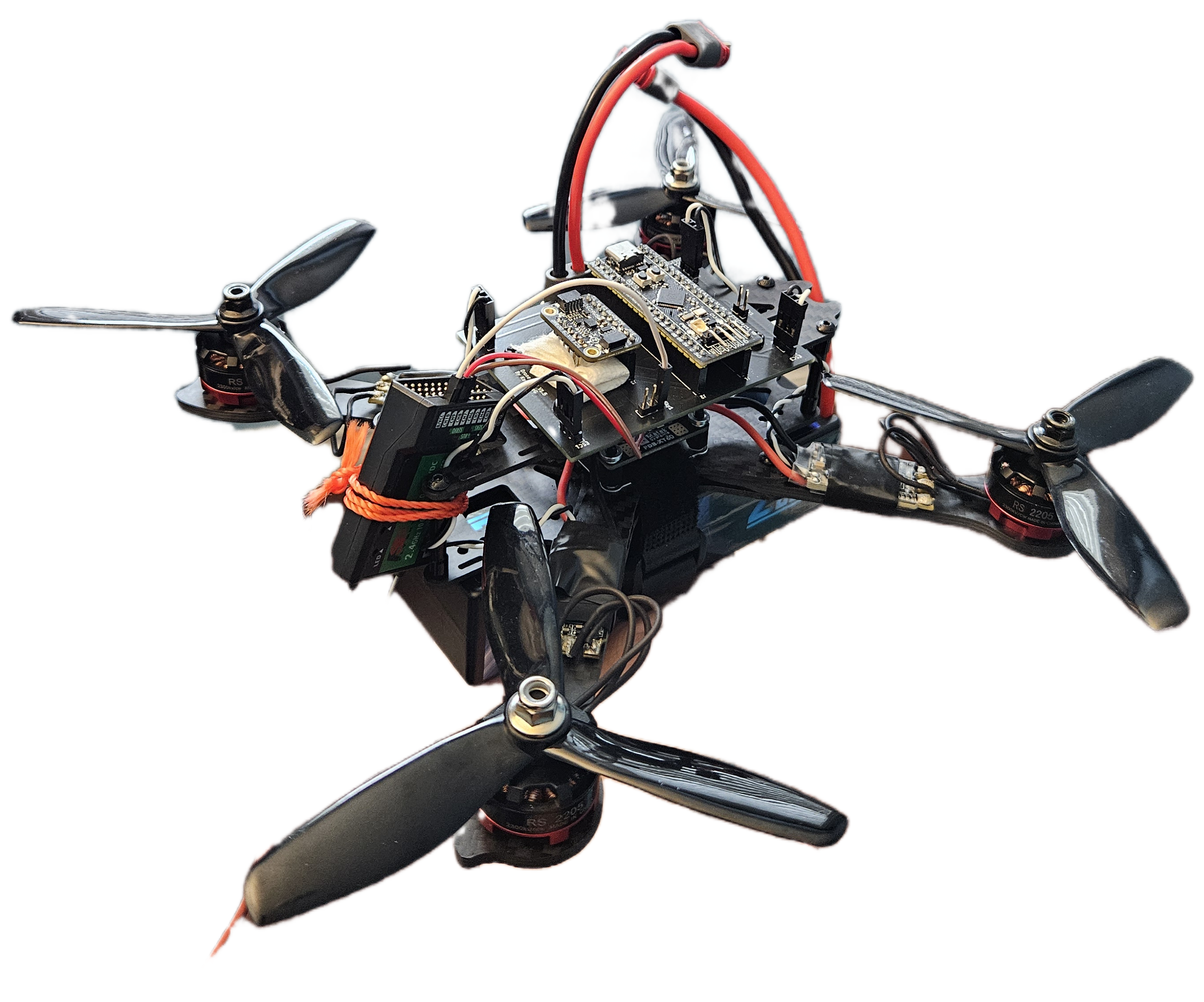
Current Issues
While the drone is assembled, stable flight has not yet been achieved. I suspect the root cause is the sporadic values from the IMU due to the vibrations from the motor messing with the accelerometer values. As a result of the IMU’s messy values, the PID is unable to get a reliable error to correct on. I’m not yet sure if this is due to my Kalman Filter implementation, if it can yet be improved with some tweaks on the R or Q values, or if I may have to switch to a different Kalman Filter crate such as yakf. This issue can be observed in the video below and the program’s output.